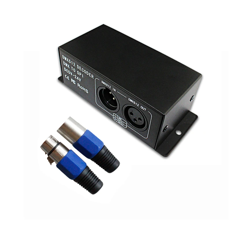
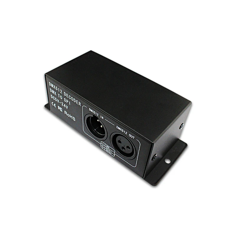
DMX512 signal decoder using advanced microcomputer control technology, the widely used DMX512/1990 standard digital control signal into a variety of LED control chip control signal. Can be connected with the DMX digital console, and can increase the decoder constantly expanding the output channel, in order to achieve more dimming or a variety of program changes. When the decoder is not connected with the DMX console, the machine can be used as a synchronization controller, and can be used for the synchronization control of a plurality of decoders and LED lamps.
Technical Parameters
This product is in compliance with DMX512 protocol, and compatible autoindex addressing and manual establishment address.
Each universal DMX controller takes up 3 DMX addresses. It adopts 2 ways (auto-index addressing and code switch) to set up the address. When adopting the auto-index addressing, all switches are "off" status. When adopting the code switch to set up address, the 10th bit(FUN) is "off" status, and other 9 bits are binary value code switch which are used to set up the DMX starting address code. The first bit is the lowest order bit, and the ninth is the highest order bit. That can set up 511 address codes. The DMX starting address code is equal to the sum of 1st to 9th bit. If move down one bit of code switch ("ON" set "1"), you can get the place-value of this bit. If move up (set "0"), the place-value is 0. For example: if you want to set up DMX starting address code for 73, you should move down the 7th, 4th, and 1st bit of code switch for "1", and others for "0", Then the place-value's sum of 1st to 9th bit is 64+8+1. That is to say, the DMX512 starting address code is 73. (The correspondence dials code position is as follows)
To choose the channel from the Dial in-line Package(DIP) Switch:
1. Example 1:
Like figure 1, to set up the DMX starting address code for 37, should move down the 6th, 3th, 1st bit for "1", others for "0". Then the place-value's sum of 1st to 9th bit is 32+4+1, as is for 37.
2. Example 2:
Like figure 2, to set up the DMX starting address code for 328, should move down the 9th, 7th, 4th bit for "1", others for "0". Then the place-value's sum of 1st to 9th bit is 256+64+8, as is for 328.
Other function's direction for use
1.Test function:
The DIP switch's 10th bit is "FUN", for built-in function key. When "FUN"="OFF", is for DMX decoder function. This is used to adopt DMX signal.
1-9 switch OFF: black
Switch 1=ON: Full color flutter
Switch 2=ON: Sub seven color move back-for-ward direction
Switch 3=ON:Sub seven color jump and move back-for-ward
Switch 4=ON: Sub seven color background move back-for-ward
Switch 5=ON: Sub seven color background move single direction
Switch 6=ON:Sub seven color stretch to single direction
Switch 7=ON: Sub seven color background overlay to left and right
Switch 8=ON: Sub seven color spread to single direction
Switch 9=ON:Sub seven color water move to left and right
Three. Conjunction Instruction:
Model 6803/2801 foreign output LPD6803 / WS2801 control signal, need four wires, the four lines, respectively:
Model 2811, 2812, 1903, 1809, foreign output 2811/2812/1903/1809 of the control signal, need three lines, the three lines, respectively:
Q1: Are you a factory or trade company?
A :We are a factory, we have a long-term relationship with domestic led lights factories & international wholesalers.
Q2: What's your main products?
A: Our main products cover LED WI-FI/RF/IR/Wire Controller, LED Amplifier, DMX Decoder, led strips.
Q3: What's your market?
A: We have a professional R&D team, Provide our customers the best solution is our mission.
Q4: Can you custom-made products?
A: Yes, we can customized it with your brand.
Q5: What about the lead time?
A: Sample needs 3days.
Q6: Do you have any MOQ limit for led dimmer order?
A: 100pcs.
JM-DMX512 3CH
JM-DMX512-DP 3CH
RGB DMX512 Decoder
Input Voltage: DC12-24V
Output Current: 4A*3CH
Buttons and Digital Display
JM-DMX-03
RGB DMX512 Decoder
Input Voltage: DC12-24V
Output Current: 8A*3CH
Buttons and Digital Display


