


Electronic ballast for uvc lamp
1. Brief Introduction
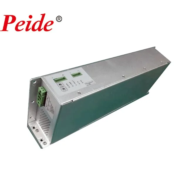
LPCU-1PH-A-3 is a high frequency electronic ballast, with high performance. It starts and drives middle pressure gas discharge lamp, which has dimming control system as well. How do it works shows at below:

2.Working conditions
Environment temperature:-5℃~+5
Relative humidity :≤95%
Altitude≤1500M
Meet IEC61373-2010 standard requirement
3.Electric parameters
LPCU-1PH-A-3 | |
Lamp power(max) (Output power) | 3kW |
Lamp voltage (Output voltage) | 300V-500V (depend on the lamp) |
output current | <8.6A |
Input voltage | 206-278VAC,single phase |
Input current | 17A(Max)typical valve |
Input frequency | 46-63Hz |
Power factor | 0.98(Typical value) |
Efficiency | >94%(Typical value) |
Harmonic current distortion | <5%(Typical value) |
Range of output power | 15%-100% |
Output frequency | 40-200kHz |
Ignition voltage | 1650Vp |
Protect function | Output short circuit protection,Open load protection,Output over voltage protection,Input over voltage protection,Input undervoltage protection,high temperature protection |
Lamp monitor | Current Monitor,voltage monitor |
Control way | IO(Compatible with PLC), CAN open, RS485(MODBUS) |
Working environment temperature | -5℃~+55℃ |
High humidity | 90% |
Cooling way | Forced air cooling,water-cooling |
Protection class | IP20 |
Size | 329*135*65 |
Weight | 4kg |
4. Electrical interface
1.Input port
Connector:PC 5/ 3-STF1-7,62 – 1777846
2.Output port
Connector:PC 5/ 3-STF1-7,62 – 1777846
3.Control port A
Connector:Phoenix MC 0,5/8-G-2,5
Connected with PLC IO,Read “5-control way”
4.Control port B
Connector:Phoenix MC 0,5/7-G-2,5
CAN BUS, RS422/RS485 Communication interface. Read “5-control way”
5.Control way
This Model ballast has three control ways of PLC I0 Hard wire, CAN Bus communication, RS485/RS422 BUS Communication, chosen by code switch.
As code switch shows above, it stands for number 17.
Number meaning on Code switch
Code switch value | Control way |
0 | hard wire control |
Non O | CAN bus/RS422 bus communication control Code switch value is the communication address
|
1.Hard wire control
Control port A connected with IO of the PLC,using the PLC to control the ballast.
1.1 pin definition
Pin | Function | Direction | Type | Description |
1 | PLC COM (0V) | Input | 0V | the cathode of external power |
2 | Must Dangling |
|
|
|
3 | Fault code 1 | Output | Open connector |
Low level means fault(driver fault) |
4 | Fault code 2 | Output | Open connector | Low level means fault(system fault) |
5 | Fault code 3 |
Output | Open connector | Low level means fault(indicator light fault) |
6 | START/STOP | Input | 24V | The anode of external power |
7 | Lamp light on signal | Output | Open connector | Low level means lamp works |
8 | Dimming control | Input | PWM | Duty ratio controls power |
1.2 Controller PLC connecting wire grid
1.3 lighting
1.3.1 Control port A Pin 6 connect with 24V, ballast starts output.
1.3.2 lights on all, control port A Pin 7, output low level
1.4 Dimming control
Exterior PWM signal enters into Ballast, ballast starts dimming control. PWM signal frequency scale: (1KHZ-3KHZ)
PWM Duty ratio | Lamp Power |
<10% | 450W |
10% | 450W |
97% | 3000W |
100% | 3000W |
2.CAN bus control way
Read “LPCU-1PH-A-3 CAN OPEN”protocol
3.RS422/RS485 bus control way
Read “LPCU-1PH-A-3 MODBUS”protocol
6. LED lamp indication
The ballast has five led indicator lights.
Name | Description |
RUN | Supply power, “RUN” Lights on, ballast operates. |
LAMP | Indicator light flashes, lamp is on the process of lighting on. Indicator light on stably, lamp finishes starting. Indicator light off, lamp off. |
FAULT | Indicator light on, fault happens. (Ballast default or lamp default) |
TX | Indicator light flashes, communication data is sending. (CAN BUS OR RS485 BUS) Indicator light doesn’t flash, no data is sending. |
RX | Indicator light flashes, communication data is accepting. (CAN BUS OR RS485 BUS) Indicator light doesn’t flash, no data is accepting. |
7.Dawing of overall dimensions
OFFICE ENVIRONMENT
CERTIFICATES
