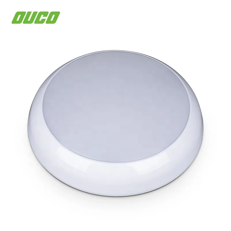
LED 2D Bulkhead Circular fixture multiple function ip65 vapor proof

| PACKAGING CONTENTS | TECHNICAL DATA | |||||||||||||||||||||||||||||||||||
|
|
| ORDERING MATRIX | |||||||||||||||||||||||||||||||||||
| BL2D | 08 | - | 3000 | IC | |||||||||||||||||||||||||||||||
| Model | Wattage | Color Temperature | Occupancy Sensor | ||||||||||||||||||||||||||||||||
| | 08 | 8 W | 3000 | 3000 K | IC | Driverless | |||||||||||||||||||||||||||||
| 10 | 10 W | 4000 | 4000K | DR | LED Driver | ||||||||||||||||||||||||||||||
| 12 | 12 W | 5000 | 5000K | EM | Emergency Model | ||||||||||||||||||||||||||||||
| 6500 | 6500K | MS | Microwave Sensor | ||||||||||||||||||||||||||||||||
| PRODUCT SPECIFICATION | |||||||||||||
| |||||||||||||
| Product Number | Size W×L×H (cm) | Wattage (W) | Efficacy (LPW) | Lumens (LM) | |||||||||
| BL2D15 | 175 × 175 × 55 | 15 | 80 | 1200 | |||||||||
| BL2D18 | 211 × 211 × 55 | 18 | 80 | 1440 | |||||||||
| BL2D24 | 211 × 211 × 55 | 24 | 80 | 1920 | |||||||||
| INSTRUCTIONS |
| Please read carefully before installation and retain 'instructions for future reference. If you are in any doubt about installing this product, consult a qualified electrician. Fittings must be installed by a competent person in accordance with current IEE Wiring Regulations (BS7671). This product should not be modified. Any modification will invalidate the warranty and may render the product unsafe. |
| FUSE VALUE |
| This fitting can be connected to a lighting circuit protected by a 5A fuse or 6A residual current device; alternatively it can be connected to a ring main by means of a fused connection fitted with a BS 1362 3A fuse. This product is only suitable for connection to 220 / 240V, 50 Hz supply and in accordance with Local Wiring and Building regulations. For domestic use only. BEFORE COMMENCING INSTALLATION ENSURE THE POWER SUPPLY IS SWITCHED OFF AT THE FUSE BOX AND FUSE IS REMOVED TO PREVENT ACCIDENTAL SWITCHING. TURNING THE LIGHT SWITCH OFF IS NOT SUFFICIENT. |
| WHAT TO DO |
| • This fitting is suitable for use indoors or outdoors. It is rated IP65 and should not be immersed in water or exposed to water jets (eg pressure washers). • The product should be ceiling or wall mounted at a height of at least 1.5mtrs from the ground. • This product is NOT suitable for bathroom zones 0 and 1. • If fitting in a bathroom the product must be supplied via a 30mA residual current device (RCD) and installed by a competent person in accordance with current IEE Viring Regulations (657671) and local building regulations. If in doubt consult a qualified electrician. •The chosen location should allow for the product to be securely mounted and safely connected to the mains supply (lighting circuit). • The product must be securely fixed to the mounting surface using the screws supplied. The plugs supplied are suitable for masonry only. Other fixings (not supplied) should be obtained for cavity walls etc. • This product is only suitable for installation on surfaces of normal filammability (e.g. masonry, wood). It is not suitable for use on highly flammable surfaces (e.g. polystyrene, plastic, flammable coatings). |
| INSTALLATION & WIRING |
| • Remove the diffuser/lens by holding the base securely and twisting to unlock/release. • Partically unscrew the 3 fixing screws and twist the metal plate to remove from the base. • Choose which mounting holes to use and pierce / knock-out with an appropriate tool. • Pierce the rubber gland on the rear of the unit (base) with an appropriate tool. • Using the backplate as a template - mark the position of the drill holes on the mounting surface. Drill with a suitable drill bit and plug the mounting holes with suitable wall plugs. Take care not to foul any mains cables or pipes below the surface while drilling. • Bring the incoming mains supply through the rubber gland. If wall mounted, it is recommended that the entry hole be located on the lower half of the unit. • Insert the wall plugs and secure the unit to the mounting surface by applying the metal washers then rubber washers and finally the screws provided. • Strip 8mm (approx) of insulating wire from the supply cable to expose the metal conductor. Connect the incoming 'LIVE' (BROWN or RED) to the terminal marked '1 (p.L)’ Connect the incoming 'NEUTRAL' (BLUE or BLACK) to the terminal marked 'N' Connect the incoming 'EARTH' (BARE/GREEN & YELLOW) to the terminal marked with the Earth Symbol Important: This product is Class I and MUST be earthed. If no earth feed wire is available, please consult a qualified electrician. • Ensure that connections are tight and no loose strands of wire are left out of the connections. • Reattach the metal plate to the backplate (base) with the 3 fixing screws previously loosened. • Reattach the diffuser / lens by placing the small lugs on its inner into the recesses on the outer edge of the base and and twisting to lock/secure. • Installation is now complete. Replace the fuse-at the mains and switch on to test. NOTE — THIS PRODUCT IS NOT SUITABLE FOR USE WITH A DIMMER |


