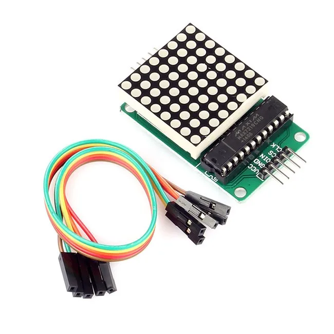
The MAX7219 is an integrated serial input/output common-cathode display driver that connects a microprocessor to an 8-bit digital 7-segment LED display. It can also be connected to a bar graph display or 64 separate LEDs. It includes an on-chip B-type BCD encoder, multi-channel scan loop, segment word driver, and an 8*8 static RAM to store each data. Only one external register is used to set the segment current of each LED.
A convenient four-wire serial interface can be connected to all common microprocessors. Each data can be addressed without any need to overwrite all displays when updating. The MAX7219 also allows the user to choose to encode or not encode each data.
The entire device includes a 150μA low-power shutdown mode, analog and digital brightness control, a scan limit register that allows the user to display 1-8 bits of data, and a detection mode that allows all LEDs to illuminate.
Only need 3 IO ports to drive 1 dot matrix! No flicker when the dot matrix is displayed! Support cascading!
Module parameters:
1. A single module can drive an 8*8 common cathode matrix
2. Module working voltage: 5V
3. Module size: length 5 cm X width 3.2 cm X height 1.5 cm
4. With 4 fixing screw holes, 3mm aperture, can be fixed by our M3 copper column
5. Module with input and output interface, supporting multiple module cascade
Wiring instructions:
1. The left side of the module is the input port and the right side is the output port.
2. When controlling a single module, you only need to connect the input port to the CPU.
3. When multiple modules are cascaded, the input of the first module is connected to the CPU, the output is connected to the input of the second module, the output of the second module is connected to the input of the third module, and so on. ..
Take 51 MCU as an example:
VCC → 5V
GND → GND
DIN → P22
CS → P21
CLK → P20
Payment Terms
1) You can pay for your purchase order by , WesternUnion, MoneyGram, Escrow, Trade Assurance, T/T, Alipay or Cash.
2) The unit price we provided not included any shipping cost or payment charges. We can offer a discount according to your purchase order quantity.
3) We are not responsible for any import fees or customs taxes.
Shippment Terms
1) We will pack and send your goods within 1-3 working days after we confirmed your payment. For quickly packing and sending, please tell us when you finish the payment.
2) We will inform you the lead time if we have to purchase from manufactory.
3) We usually ship by DHL, UPS, TNT, FedEx, Aramex or EMS. It usually takes 3-7 days to arrive. Air cargo and sea shipping are aslo optional.
4) We need your shipping information including your name, address and phone number for shipping your parcel.
5) Tracking number will be shared with you when we got it from the logistics company.
Quality Warranty
1) Our products are all original and new from manufacturer. It must be work if the model number is correct.
2) We offer 30-90 days warranty to our products.
3) During the guarantee period, if the items you purchased from our store are out of perfected quality, pls notify us within 7 days after delivery, we will return the new products when we got your message.


