


- Place of Origin:
- CHINA
- Brand Name:
- SUNWIND
- Model Number:
- 2H556
- Motor Type:
- Stepper Motor
- STEPPING MOTOR DRIVER:
- STEPPER MOTOR DRIVER
- Supply Ability:
- 100000 Set/Sets per Week
- Packaging Details
- PAPER CARTON SUITABLE FOR THE AIR/SEA/LAND TRANSPORTATIONS.
- Port
- SHENZHEN
- Lead Time:
Quantity(Sets) 1 - 1000 >1000 Est. Time(days) 15 To be negotiated
a4988 stepper motor driver DC50V,5.6A Stepper Motor Driver,2H556 stepper driver
stepper motor driver,servo driver,driver integrated servo motor,automation products,setpper motor controller,3-axis stepper motor controller
The 2H556 is a excellent performance microstepping based on pure-sine current control.With above technology and the self-adjustment function(self-adjust current control) to various motors, keep the driven motors run with low noise,less heating, smoother movement and better performances at higher speed than other drives in the markets.it is adapt to driving 2,3,4 phases hybrid stepper motors.
2H556 Stepper Motor Driver Features
High Efficiency
Excellent high speed performance
Max DC50V
Max output 5.6A
Self-adjustment function
Pure-sine current control
300KHz Max Pulse input frequence
Suitable for TTL and optically isolated input
Auto idle current reduction
15 steps resolutions in decimal binary, max 25000 steps/rev
Suitable for 2 ,3, 4 phases motors
Support PUL/DIR and CW/CCW modes
Short-voltage protection, over-voltage protection, over-current protection
2H556 Stepper Motor Driver Specifications
Electrical Specifications (Tj: 25oC~77oC)
Parameters | 2H556 | |||
Min | Typical | Max | Unit | |
Output current | 1.4 | - | 5.6(3.0RMS) | A |
Supply voltage | +20 | +36 | +50 | VDC |
Logic signal current | 7 | 10 | 16 | mA |
Pulse input frequency | 0 | - | 300 | kHz |
Isolation resistance | 500 |
|
| Mohm |
Connector P1 Configurations
Pin Function | Details |
PUL+ | Pulse signal:In single pulse (pulse/direction) mode, this input represents pulse signal, each rising or falling edge active (set by inside jumper J1); 4-5V when PUL-HIGH, 0-0.5V when PUL-LOW. In double pulse mode (pulse/pulse) , this input represents clockwise (CW) pulse,active at high level or low level (set by inside jumper J1, J2). For reliable response, pulse width should be longer than 1.5µs. Series connect resistors for current-limiting when +12V or +24V used. The same as DIR and ENA signals. |
PUL- | |
DIR+ | DIR signal:In single-pulse mode, this signal has low/high voltage levels, representing two directions of motor rotation; in double-pulse mode (set by inside jumper J3), this signal is counter-clock (CCW) pulse,active at high level or low level (set by inside jumper J1, J2). For reliable motion response, DIR signal should be ahead of PUL signal by 5µs at least. 4-5V when DIR-HIGH, 0-0.5V when DIR-LOW. Please note that rotation direction is also related to motor-drive wiring match. Exchanging the connection of two wires for a coil to the drive will reverse motion direction. |
DIR- | |
ENA+ | Enable signal:This signal is used for enabling/disabling the drive. High level (NPN control signal, PNP and Differential control signals are on the contrary, namely Low level for enabling.) for enabling the drive and low level for disabling the drive. Usually left UNCONNECTED (ENABLED). |
ENA- |
Connector P2 Configurations
Pin Function | Details |
+V | Power supply, 20~50 VDC, Including voltage fluctuation and EMF voltage. |
GND | Power Ground. |
A+, A- | Motor Phase A |
B+, B- | Motor Phase B |
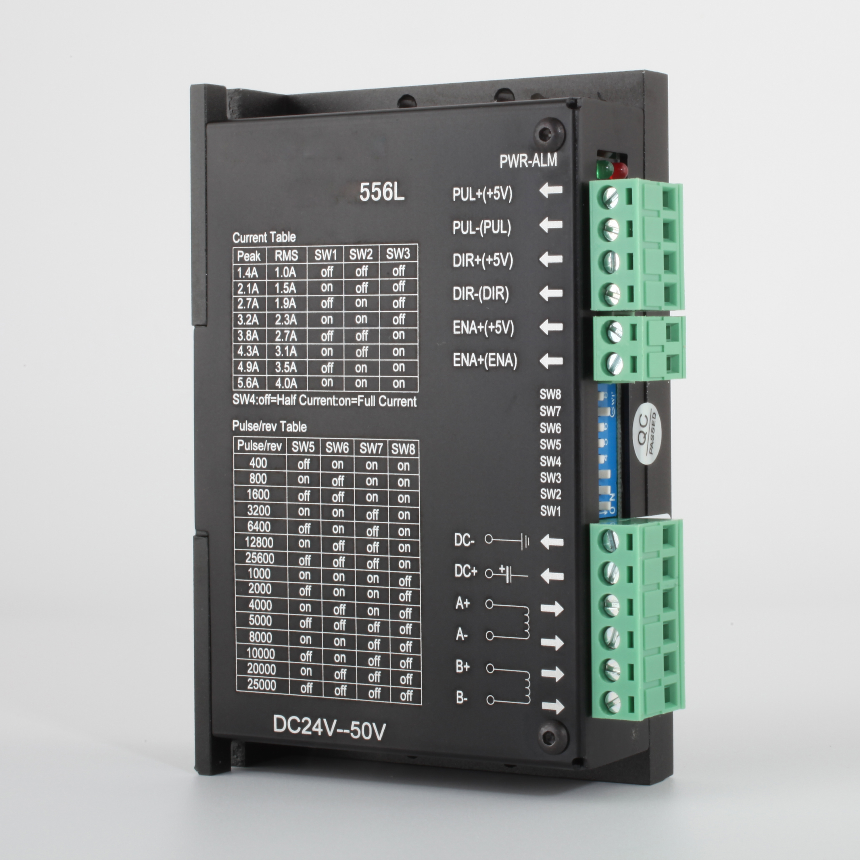
Microstep and Current
The drives uses an 8 bits DIP switch to set stepper motor resolution and motor operating current, as shown below:
Dynamic Current(1/2/3) Microstep Resolution(6/7/8)
1 | 2 | 3 | 4 | 5 | 6 | 7 | 8 |
Standstill Current(4,Half/Full)
Microstep Resolution Selection
Microstep resolution is set by SW5, SW6, SW7, SW8 of the DIP switch as show in following:
Microstep | Steps/rev.(for 1.8°motor) | SW5 | SW6 | SW7 | SW8 |
2 | 400 | off | on | on | on |
4 | 800 | on | off | on | on |
8 | 1600 | off | off | on | on |
16 | 3200 | on | on | off | on |
32 | 6400 | off | on | off | on |
64 | 12800 | on | off | off | on |
128 | 25600 | off | off | off | on |
5 | 1000 | on | on | on | off |
10 | 2000 | off | on | on | off |
20 | 4000 | on | off | on | off |
25 | 5000 | off | off | on | off |
40 | 8000 | on | on | off | off |
50 | 10000 | off | on | off | off |
100 | 20000 | on | off | off | off |
125 | 25000 | off | off | off | off |
Current Settings
The first three bits (SW1, SW2, SW3) of the DIP switch are used to set the dynamic current. Select a setting that closest to your motor"s required current.
Peak Current | RMS Current | SW1 | SW2 | SW3 |
1.40A | 1.00A | off | off | off |
2.10A | 1.50A | on | off | off |
2.70A | 1.90A | off | on | off |
3.20A | 2.30A | on | on | off |
3.80A | 2.70A | off | off | on |
4.30A | 3.10A | on | off | on |
4.90A | 3.50A | off | on | on |
5.60A | 4.00A | on | on | on |
Note:Due to motor inductance, the actual current in the coil may be smaller than the dynamic current setting, particularly in high speed condition