


- Place of Origin:
- CHINA
- Brand Name:
- SUNWIND
- Model Number:
- SW0808024
- Motor Type:
- AC Motor
- 2.4NM SERVO MOTOR DRIVER:
- 800W SERVO MOTOR DRIVER
- Supply Ability:
- 1000000 Set/Sets per Week
- Packaging Details
- FOAM&PAPER CARTON SUITABLE FOR THE AIR/SEA/LAND TRANSPORTATIONS.
- Port
- SHENZHEN
- Lead Time:
Quantity(Sets) 1 - 1000 >1000 Est. Time(days) 12 To be negotiated
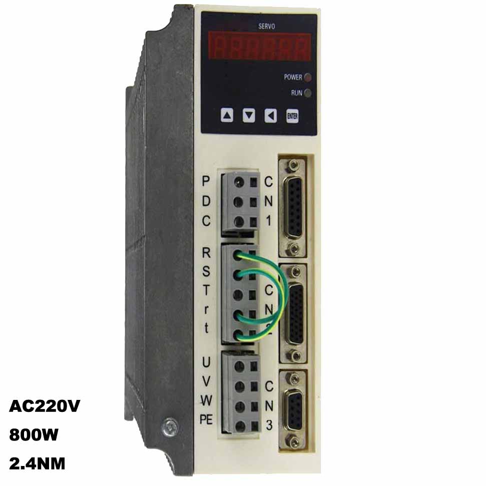
800W,2.4NM AC220V Servo Motor Driver
- Product Description
SW0808024 800W,2.4NM,AC220V Servo Motor Driver, Servo Motor Driver factory.
SW6AA030M2 Servo Motor is a new generation of general-purpose servo motor driver, which is optimized and improved on the basis of SW6 series servo drivers. Adhering to the series SW6 series servo drivers excellent quality, more Reliable and more convenient. More mature and stable, rich and completely information. The servo driver add to 485 new communication functions, more convenient and reliable connection with the host PC and controller software.
Low-Inertia Series
SW0808024 800W,2.4NM,AC220V Servo Motor Driver’s Features
- 1. Environment temperature for the servo drive: 0~55°C;
- 2. Humidity: 90%RH;
- 3. Vibration: 4.9m/s2;
- 4. No freezing or condensing;
- 5. To ensure the long term reliability, please keep the environment temperature lower than 45°C;
- Interface to analog command input circuit:
- The analog signals include speed command signal and torque command signal. The impedance of command input is about 40kΩ and the maximum allowable voltage of input signal is ±10V;
- Interface to input circuit:
- Connect with the transistor circuit of relay or collector open circuit. To connect with relay, please select the relay for micro current; otherwise, it may cause bad contact;
- Interface to bus drive output circuit:
- Output the two-phase (A and B) pulse output signal (PAO, /PAO, PBO, /PBO) and origin pulse signal (PCO, /PCO) through the bus drive output circuit. It is usually used when the top device composes the position control system. On top device side, please receive with wire receiving circuit;
- Interface to output circuit:
- The servo alarm, servo ready and other output signals for sequence are composed with the output circuit of the optical coupler. Please connect with relay and wire receiving circuit. Connect with relay and wire receiving circuit.
SW0808024 800W,2.4NM,AC220V Servo Motor Driver’s Parameters
Parameter No.
Parameter name
Applicable mode
Parameter range
Default
Unit
Remark
PA-01
Control mode
1∼6
1
Select the control mode of drive through this parameter
1: Position control mode (QS5AA015B/20B/30B/20M/30M/50M)
2: Analog speed control mode (QS5AA020M/30M);
3: Speed trial control mode (QS5AA015B/20B/30B/20M/30M);
4: JOG trial control mode (optional)
5: I/O point control mode, ALR, CLE, INH select 8 speeds from PA51-58
6: Torque control mode
For position control mode, the position command inputs from pulse input port; for analog speed control mode, the speed command inputs from the PIN of input port and correspond to different speed according to positive and negative level (±10V); for speed trial mode, it runs in SPEEDTEST state; for JOG trial control mode, it runs in JOGTEST modePA-02
Speed loop ratio constant (mid-high speed)
10∼1000
200
Speed loop ratio constant; set the ratio gain of speed loop adjuster through this parameter. The higher this value is, the higher the gain and system rigidity are. Please set the parameter value according to the load and default reference value of the drive. This parameter should be as high as possible under the condition that the system doesn"t oscillate
PA-03
Speed loop integral constant (mid-high speed)
10∼1000
100
Speed loop integral constant; set the integral time constant of speed loop adjuster through this parameter. The higher this value is, the higher the rigidity is. The higher the inertia is, the higher this value is. Please set the parameter value according to the load and default reference value of the drive. This parameter should be as high as possible under the condition that the system doesn"t oscillate
PA-04
Acceleration time constant
6∼1530
6
ms
Acceleration time constant; this value is the acceleration time of the motor from 0rpm to 1000rpm.
PA-05
Deceleration time constant
6∼1530
6
ms
Deceleration time constant; this value is the deceleration time of the motor from 0rpm to 1000rpm
PA-06
Position loop gain
Position control
40∼500
160
Position loop gain; this parameter is used to set the ratio gain of position loop adjuster. The higher this value is, the higher the gain and rigidity are. Under same frequency command pulse, the position delay is smaller. Too higher value may cause oscillation or overshoot.
PA-07
Position loop feedforward coefficient
Position control
0∼100
10
Position loop feedforward coefficient; this parameter is used for feedforward gain adjustment of position loop. The higher this value is, the smaller the position delay is. The smaller this value is, the slower the response is.
PA-08
Default display contents
1∼15
1
Default display contents; this parameter is used to set the default display content of the drive after power on.
PA-09
Position command pulse mode selection
Position control
1∼2
1
Pulse mode selection; this parameter is used to set the default position loop pulse input mode of the drive. 1: command pulse + direction; 2: CW, CCW double-pulse
PA-10
Position command pulse direction reverse
Position control
1∼2
1
Position command pulse direction reverse; this parameter is used to reverse the motor direction
PA-11
Position over tolerance detection range
Position control
1∼3000
900
*10
- Easy setting
Real-time auto-tuning function machine characteristics is automatically measured to set necessary servo gain. Optimum setting can be obtained in a short time;
- ALL-in-one control
Position, Speed , and Torque control can be selectively used by switching user parameters;
- Harmonic suppression
DC reactor connectors are standard equipments to suppress power harmonic;
- Built-in operator with six-digit indication LED
Setting and monitoring in work place are easy. Parameters can be set by using the built-in operator;
- Vibration control
Vibration control functions, such as high-order torque command low-pass filter, broadband 2nd order notch filter, and vibration control observer provide high-response and low-vibration operation;
Positioning stabilization reduction
New speed controller is employed to substantially shorten the positioning stabilization time(1/5of existing model);- Command track control
A new position and speed controller is employed to improve the tracking ability of position control twice better than that of existing model. In addition, almost zero position deviation is achieved;
Test operation (JOG function)
JOG function is installed to check the connection between motor and amplifier allowing easy test operation without inputting position and speed commands.Imput Signals:
Signal namePIN No.
Function
Reference
+24VIN
9
Control power supply input for sequence signal: +24V power supply is provided by the user.Operative voltage range: +11V ~ +25V
4.2.4
SON
10
Servo ON input; after valid, receive control command in 50ms
4.5.2
INH
11
Command pulse prohibited
FSTP
12
Prohibit forward rotation driving
4.1.2
RSTP
13
Prohibit reverse rotation driving
ALR
14
Alarm clear: relieve servo alarm state
4.5.1
CLR
15
Reset signal input: clear deviation counting while position control
4.2.2
RIL
16
External limit input of forward rotation torque
4.1.3
FIL
17
External limit input of reverse rotation torque
4.1.3
VIN
19
20Speed command input: ±10V
4.2.1
TIN
21
22Torque command input: ±10V
4.2.8
CZ+
CZ-28
29Programmable output
4.2.2
/PULS
PULS
/SIGN
SIGN24
25
26
27Command pulse input, optical coupling isolation
Input mode
*Symbol + pulse
*CCW/CW pulse4.2.2
Output signal:Signal name
PIN No.
Function
Reference
1
2COIN-
COIN+Location complete signal output; when the signal deviation counter value is in specified location range, the location complete output is ON
3
4ALM+
ALM-Alarm output
4.5.1
5
6RDY+
RDY-Servo ready output
7
8BRK+
BRK-Brake output
PAO+
PAO-
PBO+
PBO-
PCO+
PCO-34
35
32
33
30
31Phase A signal
Phase B signal
Phase C signal2Two-phase pulse (phase A and B) conversion coder output signal and origin pulse (phase C) signal
4.2.3
FG
shell
If the shielded wire of the signal input/output cable is connected to connecter shell, it may be connected to frame earth wire. (earth wire)