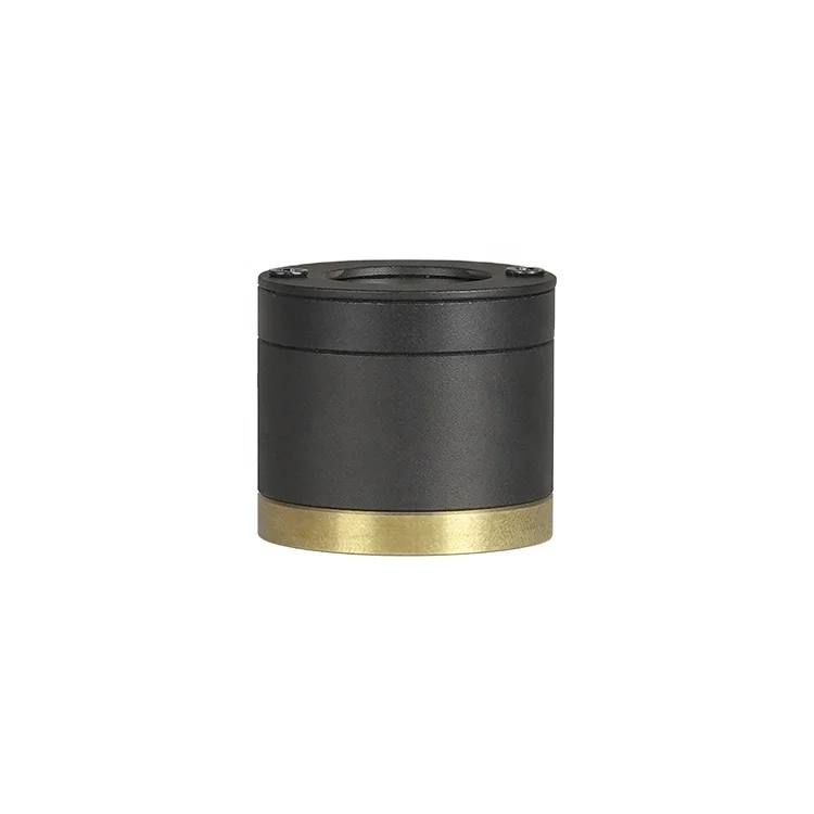
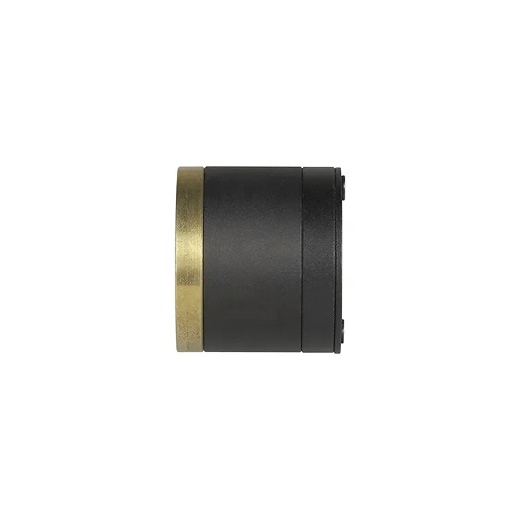
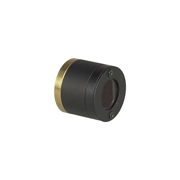
| Product Name | 10w white light laser module for flashlight |
| Model | SHA10 |
| Input Voltage | Available 4-5V |
| Luminous Flux | 500lm |
| Color temperature | 7000K |
| Certification | RoHS |
| Warranty | 1 year |
1. Technology overview
A brand new product designed and produced by Unionlux, SHA10 is a special illumination source of visible light based on the laser technology. With high brightness, compact design, and long lifetime, stability and strong directing property, it offers premium beam light with round spot for flashlights or long-distance searching light.
Features
Technology: High power laser stimulates phosphor to emit visible light
High luminous intensity, twice of the xenon lamp
Long lifetime, more than 10,000 hours
Without and movement component, stability and reliability
Low operating voltage, cool start
Cover visible spectrum, no IR and UV component
Luminous adjustable, support amplitude and frequency modulation
2. Performance Characteristics
2.1 Absolute Maximum Ratings
|
Item |
Symbol |
Parameter |
Unit |
|
Maximum Forward Current*1) |
IfMax |
2.7 |
A |
|
Allowable Reverse Current*1) |
Ir |
85 |
mA |
|
Storage Temperature range |
Tstg |
-40 ~ 85 |
°C |
|
Operating Temperature range *2) |
Tm |
0 ~ 65 |
°C |
Notes for the above table:
*1) Test Condition: Tm =25°C, ACC (Auto Current Control) Operation
Individual LD light source module.
*2) Refer to Figure 4.
2.2 Electrical Characteristics
|
Item |
Symbol |
Test Condition |
Min |
Typ |
Max |
Unit |
|
Threshold Current*3) |
Ith |
CW Operation |
220 |
- |
500 |
mA |
|
Forward Voltage*3) |
Vf |
If =2.5A |
4.0 |
4.4 |
5.0 |
V |
Notes for the above table:
*3) Based on CW operation.
Test Condition: Tm =25°C, ACC (Auto Current Control) Operation

Figure 1.Pin assignment
2.3 Initial Optical Parameter based on integrating sphere testing
|
Item |
Symbol |
Test Condition |
Min |
Typ |
Max |
Unit |
|
Correlated Color Temperature*4) |
CCT |
If=2.5A |
6,200 |
7,000 |
7,800 |
K |
|
Luminous Flux*4) |
Φv |
If=2.5A |
450 |
500 |
- |
lm |
Notes for the above table:
All parameters in this specification are measured by Unionlux's method and may contain measurement deviations.
*4) Test Condition: Tm =25°C, ACC, If=2.5A (CW)
2.4 Initial Optical Parameter based on spot on wall
|
Item |
Symbol |
Test Distance |
Min |
Typ |
Max |
Unit |
|
Illumination(Center Point)*5) |
EVP01 |
5M |
13,250 |
14,000 |
- |
lx |
|
EVP02 |
8M |
5,100 |
5,400 |
- |
lx |
Notes for the above table:
All parameters in this specification are measured by Unionlux's method and may contain measurement deviations.
*5) Test Condition: Tm =25°C, ACC, If=2.5A (CW)
Center Point [P0] refer to Figure 3.

Figure 2.Illumination parameters for further distance*6)
Notes for Figure 2:
*6) The illumination parameters[P0’] of 50M,100M,200M,500M and 1,000M in Figure 2. based on the simulation and do not consider the air influence.

2.5 Lifetime Characteristics
|
Item |
Symbol |
Test Condition |
Min |
Typ |
Max |
Unit |
|
Estimated Lifetime*7) |
Life |
Cumulative Failure Rate 50% |
10,000 |
- |
- |
hrs |
|
Cumulative Failure Rate 1% |
1,000 |
- |
- |
hrs |
Notes for the above table:
*7) Test Condition: Tm =65°C, ACC, If=2.5A (CW)
Calculation Method:
Estimated in the linear extrapolation by degradation rate at tested duration 1000 hrs.
Criteria for judging the defect of lifetime: Φv×0.5
Cumulative failure rate is calculated by the parameter greater than 500pcs.
2.6 Thermal Characteristics

Figure 4.Schematic diagram of measurement system
Heat Dissipation System: Ensure the temperature of the Copperplate[Tm] ≤65℃.
Calculating method of Thermal Power [Pth]: Pth = Operating Power * 75%
3. Characteristics Curves

Figure 5. Relative Luminous Flux vs. Forward Current*8)

Figure 6. Forward Voltage vs. Forward Current*8)

Figure 7. CCT vs. Copperplate Temperature[Tm] at If=1.5A(CW) *8)

Figure 8. Relative Luminous Flux vs. Copperplate Temperature[Tm] at If=2.5A(CW) *8)

Figure 9. Forward Voltage vs. Copperplate Temperature[Tm] at If=2.5A(CW) *8)
4. Spectral Power Distribution Characteristics

Figure 10. Typical normalized power vs. wavelength at Tm =25°C, ACC, If=2.5A (CW)
5. Mechanical Dimensions

Figure 11. Mechanical Dimensions*9)


