The operating principle of a heat pump is based on the physical property that "the boiling point of a fluid increases with pressure". By lowering pressure, a medium can be evaporated while an increase of pressure will lead to condensation.
For large scale industrial applications, Ammonia is the most suitable refrigerant. It is mostly used in a pump system.
Log P-h diagram
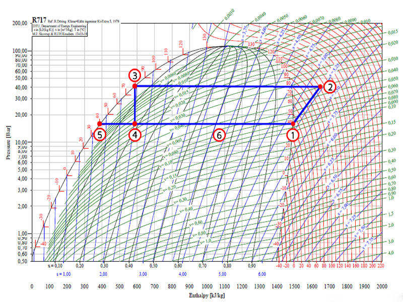
To understand the principle of operation of an mechanical heat pump, a log P-h diagram can be used. A log P-h diagram shows all state variables of the refrigerant. On the horizontal axis enthalpy (h) is shown. The vertical axis has a logarithmic scale and shows pressure. The other lines show:
· Red: Temperature [°C]
· Blue: Entropy [kJ/kg]
· Green: Specific volume [m3/kg]
The black line divides the graph according to the different states of Ammonia (NH3). On the left its fluid phase is shown. On the right side Ammonia is in its gaseous state. Below the black curve a combination of both gaseous and liquid Ammonia can be found. The area above the highest point is called the transkritical area.

The thermodynamic cycle
The log p-h diagram shows a cycle for a mechanical heat pump. The points represent the different components of the heat pump. In this diagram a heat pump with a condensation temperature of 80 °C and an evaporation temperature of 40 °C is taken as an example.
1-2 The compressor: With a compressor the pressure of the gaseous refrigerant is increased from 15 to 40 bar. Ideally the entropy (s) stays constant during this process. In reality the entropy will increase somewhat, because the electric energy needed to power the compressor is partly absorbed by the refrigerant. Due to that the temperature of NH3 gas will rise to 120 °C.
2-3 The condenser: The condenser delivers useful energy. In the condenser the superheated gas is cooled from 120 °C to 80 °C. Then condensation takes place at constant temperature of 80 °C, until all vapor has become liquid. The liquid flows to the expansion device.
3-4 Expansion device: Inside the expansion device the pressure is reduced from 40 to 15 bar. Due to the expansion a mixture of gaseous and fluid Ammonia is formed. This mixture flows to the liquid separator.
4-5/1 Liquid separator: Inside the liquid separator both fluid (5) and gaseous (1) Ammonia can be found. Its most important function is to separate the liquid and vapor. The vapor flows to the compressor; the liquid is pumped over the evaporators.
5-6 Evaporator: The liquids ammonia at the bottom of the separator is pumped over the evaporator(s). Inside the evaporator a part of the ammonia is evaporated at a constant temperature of 40 °C. The energy needed for evaporation is delivered by a source of waste heat. The mixture of liquid and vapor ammonia flows back to the separator (6) and is separated again in liquid and vapor.
Remark:
Some of the articles are taken from the Internet. If there is any infringement, please contact us to delete it. If you’re interesting in heat pump products,please feel free to contact OSB heat pump. We are your best choice.

