Brand: |
none |
Address: |
China |
Min.Order: |
none |
Supply: |
none |
Valid until: |
Long Term |
Product Details
- Input Voltage(V):
- 85-265V, 220V-240V 50-60Hz
- Lamp Luminous Flux(lm):
- 80%-100%
- CRI (Ra>):
- 85
- Working Temperature(℃):
- -20 - 40
- Working Lifetime(Hour):
- 50000
- Lamp Body Material:
- PVC
- IP Rating:
- IP65
- Place of Origin:
- Guangdong, China
- Brand Name:
- EVEN Emergency Converter
- Model Number:
- Emergency Converter
- Light Source:
- LED
- Key Product:
- Emergency Converter
- Output Current:
- 80mA-450mA
- Working life:
- 50000hours
- Material:
- Plastic
- Continuous Battery Time:
- 1~3 hours
- Usage:
- Luminaires
- Emergency Brightness:
- 30%-100%
- Bulb type:
- LED
- Battery Charging:
- 24hours
- Item Type:
- Panel Lights
- Color Temperature(CCT):
- Warm White
- LED Light Source:
- 22-24LM
- Warranty(Years):
- 3
- Lamp Power(W):
- 30
- Lamp Luminous Efficiency(lm/w):
- 230
- Supply Ability:
- 9999999 Piece/Pieces per Day Emergency Converter
- Packaging Details
- Emergency Converter insulated package
- Port
- Shenzhen/HongKong
- Lead Time:
- 5-15 days
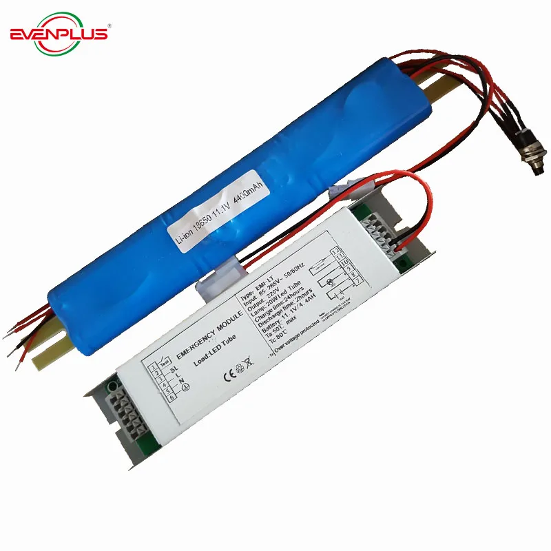
40W LED Panel Emergency Converter 1-3 hours backup time
Instruction Manual of EME-EL Emergency Pack
1. Model: EME-EL
EME-EL emergency pack is designed to convert a wide range of LED types,ideal choice for converting most standard LED luminaires and arrays containing from 2-55V LEDs in series.
This unit is designed to assort with existing LED driver and panel layout. The control circuit of
inverter monitors the mains supply, Inverter allows the charger to trickle charge the battery pack
or stand by if light works well. In the case of the emergency, Inverter automatically activate
battery backup system to illuminate the lighting in less than 0.1 second
2.Wiring Diagram


3.Product details :
LED Strip : 24W
Output Voltage :DC12V
Output Current : 2A
4.Emergency Solution:
1. According to EN60598; EN 55015; CE;
2. Deep discharge protection
3. Operation time (discharge):1hour(Customized within 1hr)
4.Lumen Factor : 50%
5.Emergency Output:DC12V/1A
6.Matched Emergency Solution : 6V/2.5Ah Ni-CD Battery + Inverter+ Metal Box+ Inner Box
5. Dimension (mm ):
Battery Size : C type (50*25mm/cell)
Inverter Size : 155*40*30mm
6.Application:
Product name: Emergency module for LED Strip
7.Specifications of Drawing, Schedule and Symbols:
L = “live”wire
N= “Neutral” wire sometimes called “nil” or “0”
Switch = a mechanical device that connects or interrupts a “life”wire to the driver.
LED Driver is an electronic device that drives the LED lighting fixture with a constant current.
SL is switched Life wire connection on the LED driver
N is the Neutral connection on the LED driver
+ on the LED driver is the positive connection from driver to the LED fixture
- on the LED driver is the negative connection from driver to the LED fixture
5.Usage range :
Hotels
Conference/Meeting rooms
Factories & Offices
Commercial Purposes
Residential/Institution Buildings
Schools, Colleges & Universities
Hospitals
Places where energy saving and high color rendering index lightings are required
9.Installation Instruction:
-Connection 1 is used for safety ground (earth)
-Connection 2 is used for connecting to the life wire of the buildings electricity network before the
switch, sensing if the life wire is “alife”
-Connection 3 is used for connecting the neutral of the buildings electricity network
-Connection 4, 5 and 6 are not used. Or connect “L” of building electricity to connection 4(SL),
and connect Driver “L”,”N”with connection 5 and 6.
-Connection 7 and 8 have a test switch
-Connection 9 (positive +) and 10 (negative -) for connecting a control LED meaning Life
electricity is connected and “alive”.
-Connection 11 (positive +) and 12 (negative -) are used to connect the battery for emergency
operation.
-Connection 13 (positive +) and 14 (negative -) are used to connect the LED system driver.
-Connection 15 (positive +) and 16 (negative -) are used to connect the LED fixture to the current driver of the module.
10.Operation
The module is capable of testing the performance of the emergency luminaire in accordance with
IEC EN61347-2-7 & EN61347-2-13.
11.Commissioning Test
Connection of the mains supply will initiate commissioning where the battery will remain on charge for an uninterrupted 24 hours. An interruption of the mains supply will impact the accuracy of emergency running duration.
12.Functional test
This test can be initiated manually by pressing the Testing Button.
13.Duration Test
A full rated duration test is carried out after charge the battery for 24 hours.
Note that start times of the tests are set based on the battery capacity.
14.Charge LED Indicator
A range of LEDs are available in red or green, diffused or clear high intensity, with or without a fitted rubber bezel or plastic clip and with various lead lengths.Check the LED charge indicator is on with the mains present and battery is being charged while inverter is working well.
Attentions:
- Pay extra attention to the negative and the positive pole of the battery in order to prevent
reverse operation, please use designated and matching batteries and ensure all wiring is done
correctly and stable before use.
- If you need to do product testing, unplug the battery pack when the emergency device is
disconnected from the mains supply, and then plug in the battery after the emergency device is
completely shut down.
- Comply with the wiring connection circuit diagram completely, prevent from over loading and
non loading in the process of use and testing.
- In order to prolong the battery powered lighting time, all indicator lights are switched off
during normal use with the emergency power system in standby mode.
- The battery is not charged before leaving the factory; please charge the battery longer than 24
hours before use.
- In general, the battery needs to be fully charged and discharged for around 3- 5 times in order
for the Ni-CD/Ni-MH battery to operate at full capacity.
8- It is detrimental for the Ni-CD/Ni-MH battery to lie idle for a long time, especially when it runs
dead. Charge the battery completely when it is out of operation for a long time. (The battery cannot
lie idle for more than three months)
Important:
It is recommended that the module is installed by a competent person ensuring the installation complies with the necessary standards. EVEN accepts no responsibility for injury, damage or loss, which may arise as a result of incorrect installation, operation or maintenance. the conversion requires an unswitched supply for charging the battery and a switched supply for a maintained conversion.Ensure that the finished converted luminaire operates within the module and battery temperature ratings.Ensure that the original luminaire components are still operating within their temperature ratings.
Note the production date of the battery.
-Charge the battery completely when it is out of operation over 3 month.
-Check the emergency module functionality for 3 month intervals.
-Replace the battery every 3 years interval


 Share
Share


Customer Reviews total 0 items