Brand: |
none |
Address: |
China |
Min.Order: |
none |
Supply: |
none |
Valid until: |
Long Term |
Product Details
- Place of Origin:
- Guangdong, China
- Brand Name:
- WELFARE
- Installation:
- signal zone or mutiti zone protection
- design for:
- hfc-227eafire suppression system co 2 fire suppressiion system
- design charges:
- free
- techincal support:
- we can supplier more sevice
- Supply Ability:
- 200 Set/Sets per Month
- Packaging Details
- Blanket or wooder
- Port
- NINGBO
- Lead Time:
Quantity(Pieces) 1 - 1 >1 Est. Time(days) 10 To be negotiated


1. Introduction
HFC-227ea fire extinguishing-agent is a clean, low toxic, isolated, effective product which makes no damages to the ozonosphere, it is a successfully developed gaseous fire-extinguishing agent until present. HFC-227ea has already been used in Europe and America and it is the fine replacement for the Halon fire extinguishing-agents.
HFC-227ea is effective with fully-immersing (total Flooding) way to put out electrical fire, flammable liquid or soluble solid fire, solid surface fire, and gas fire which supply can be cut down before extinguishing. It is to be used in place with people working or gathering. HFC-227ea leaves no residua and is conducting medium free, these features make HFC-227ea irreplaceable in locations such as computer room, telecom machine room, power transmission room, Precision apparatus room, power room, gas and oil terminal, flammable chemical and book storage, document and file storage, gold vault, etc.
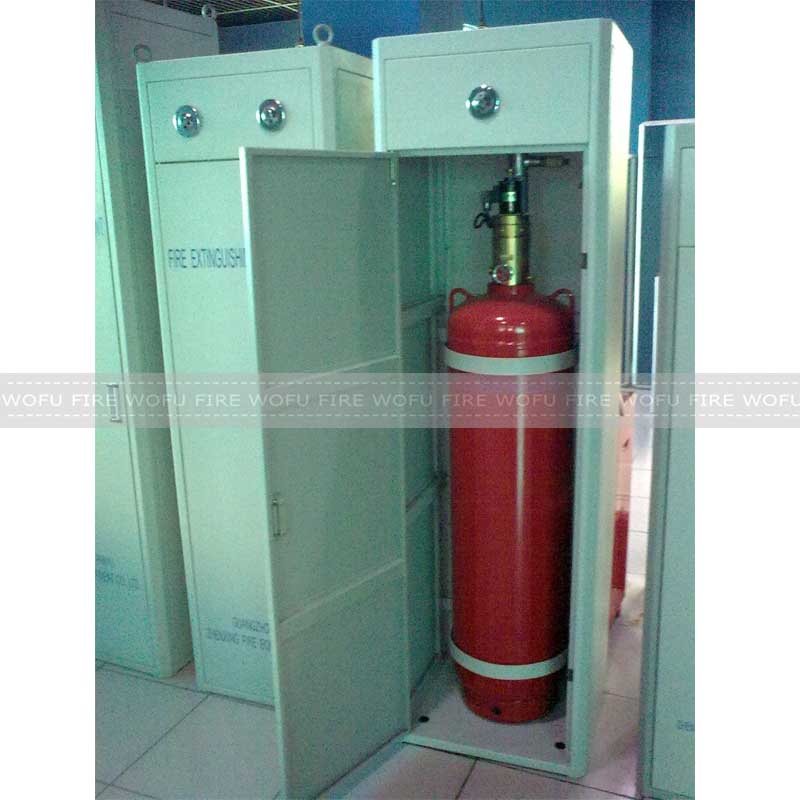
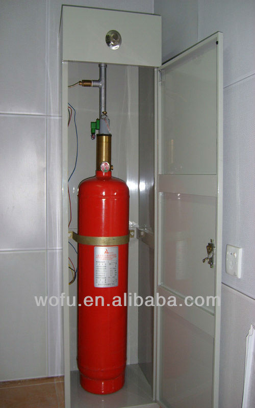
The HFC-227ea cabinet fire-extinguisher consists of container set, pipe, nozzle, signal feedback parts, checkup parts, driving parts, and cabinet. HFC-227ea can be set up as the auto fire-extinguishing system together with the fire alarm and fire controller, it can be placed in the protecting area and its portable and easy to install.
2. Main Technical Specification
Capacity | max capacity (Kg) | size L×W×H (mm) | store Pressure (20°C) | pressure releaser | discharge time | startup voltage/current | working temperature | max working pressure |
20LTR | 23 | 430×380×1050 | 2.5MPa | 4.5 ± 0.225MPa | ≤8s | DC24V/1.2A | 0°C~50°C | 3.4MPa |
40LTR | 46 | 430×380×1500 | ||||||
70LTR | 80 | 480×450×1700 | ||||||
100LTR | 115 | 530×480×1700 | ||||||
120ltr | 138 | 530×480×1880 | ||||||
150Ltr | 172 | 600×500×1880 | ||||||
180LTR | 180 | 2250*600*500 |
3. Configuration & Major Components
3.1 Major Component
3.2.1 Cabinet
Processed with fine steel thin plate, framing structure, antisepticized finish, and no visible welding marks and screws, clean-cut and durable.
3.2.2 Container(cylinder)
1) Usage:
For storing HFC-227ea fire extinguishing-agent(FM200) and is functioned with sealing, releasing, filling, and pressure venting, pressure displaying, etc.
2) Configuration:
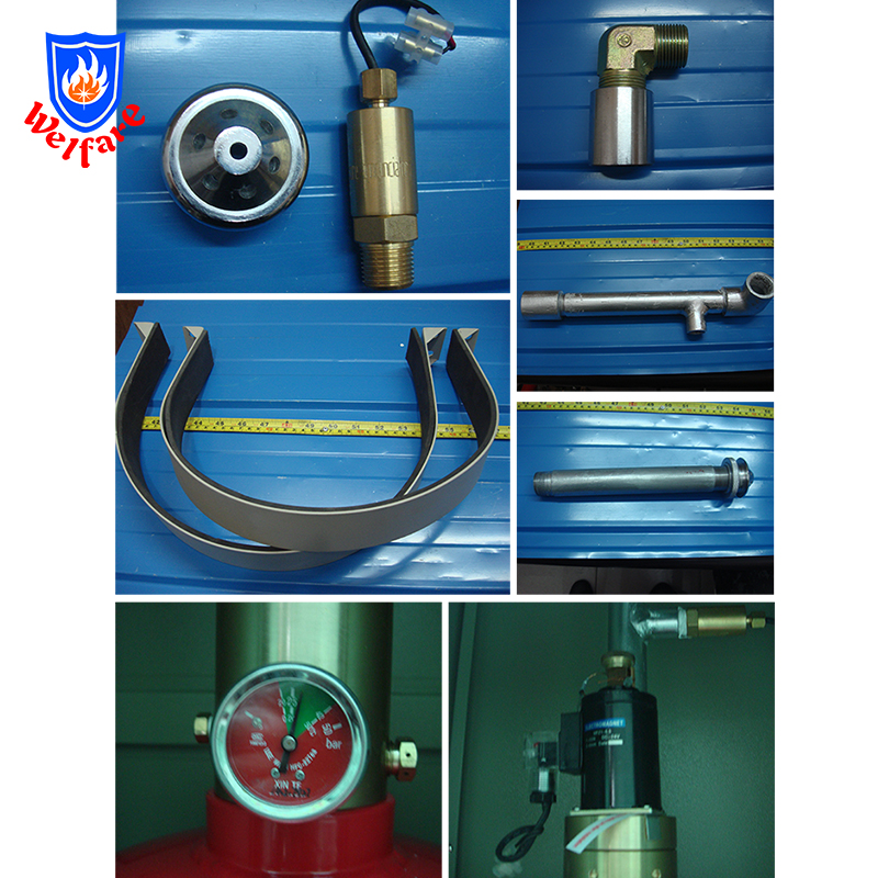
consists of container valve, siphon tube, and carton steel container. Steel container is the red epoxy painted-steel welded vessels which allow to recharge . Container valve is consisted of valve body, electrical actuator device, valve , pressure indicating component, relief device, etc. It was connected with siphon tube and installed at the top of the cylinder, the container valve can be opened electromagnetic or manually to release extinguishing agent.
3.2.3 Pressure Switch
1) Usage
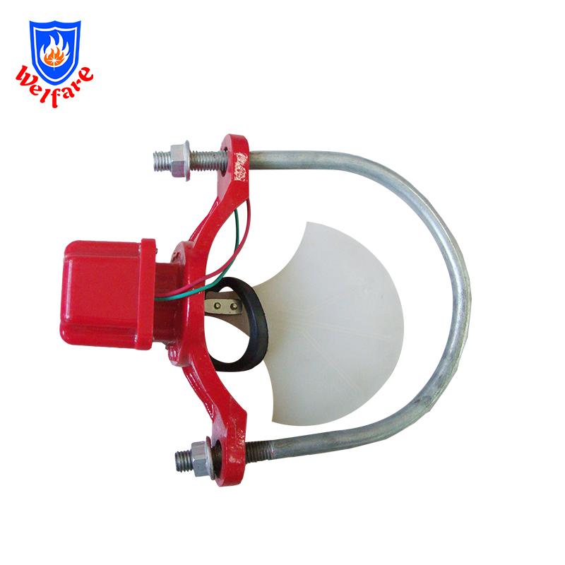
Install on the main pipe lead to the protective areas. To transfer the signal to the fire-extinguishing control panel after the gas was discharged . Fire control panel will turn on the dishcharge warning light and send the coordinated fire alert signal.
2) Structure
Consist of base, shell, locknut, signal lead wire, piston and sensitive switching. The shell and piston are made in copper alloy.
3.2.4 Nozzle
1) Usage
Be installed at the end of the fire-extinguishing pipe net. It was design to uniformly atomizing and spray the fire-extinguishing agent. The final specification was selected by the result of hydraulic computation.
2) Structure
It was optimum structural design to uniformly atomizing and spray the fire-extinguishing agent. It was made of copper alloy. The adornment was used in the area with ceiling.
4. Installation
4.1 Installing
4.1.1 Preparation
Choose the proper position before installing, make sure the installation and maintenance are easy to operate in the position, check the load capacity of floor wherever necessary.
4.1.2 Installing the cabinet
Note that the electric control cable is to be connect through the hole in the upper or lower part of the cabinet. Covering pipes should be used to protect the isolated cable. Bolts are set to each corner of the pedestal inside the cabinet which adjust the cabinet onto the floor stably.
4.1.3 Installing the container
Fasten the elbow joint to the valve of the container, the mouth of the elbow faces upward. Carry the container into the cabinet with care, use steel pipes as rollers if necessary, note that the aluminum alloy angle decoration under the cabinet is damageable.
4.1.4 Installing the pipes
Pipes and relevant parts have been installed before leaving factory, please follow the figures when install. Note that the mouth of the pipe is to be positioned right to the nozzle hole on the cabinet panel.
4.1.5 Installing the nozzle
Install the nozzle right to the mouth of the pipe through the cabinet panel, insert a screwdriver to the nozzle hole to hold the nozzle still if necessary.
4.1.6 Stabilizing the container
The steel strips inside the cabinet are used for stabilizing the container into the cabinet.
4.2 Configuring
4.2.1 Check for storage pressure
Pressure switch is turned off before leaving factory, no pressure is shown before use. The show the storage pressure, use a spanner to turn 1-2 circles anticlockwise, the index should be within the green scale. Keep the meter on after installation. Adjust meter to keep the index pointing upward.
4.2.2 Check for electromagnet function
To check for electromagnet function, unload the electromagnet from the valve with care. The core is already in functioning position when it is loosened. Put the electromagnet upside down to reposition the core whenever testing, then lay down the electromagnet and insert a small stick into the electromagnet as a positioning reference, connect power to the electromagnet with 18V or above direct current (no less than 1.5A), the core should push the stick out of the electromagnet immediately. The use of a stick can also measure how long had the core moved, so as to test whether the cutter can reach and powerful enough to stab through the sheet.
4.2.3 Safety shield
Safety shield helps to prevent misoperation of the cutter caused by transportation, installation and configuration. After finishing checking for electromagnet function and before operating, the shield must be unloaded and the four bolts of the electromagnet must be fastened, otherwise the valve of the container can not be opened. The shield can be placed inside the cabinet for future reinstallation when moving the container.
4.2.4 Testing the spouting feedback signal
The two leads of the pressure switch are non-electropolar, connect the leads to enable the simulation of spouting feedback signal.
5. Operating and Maintaining
5.1 Operating
The HFC-227ea Cabinet Fire Extinguishing System can be started up automatically or manually.
5.1.1 Auto mode
Whenever there’s smoke (or increasing temperature), the smoke (or temperature) fire detector anti-fire area is activated and sends out an individual fire signal to the gaseous fire-extinguisher controller. The controller immediately sets into the individual fire status and activates the fire alarm (or whistle alarm) to send out the individual fire signal, at this stage the control signal of starting up the fire extinguishing system is not sent yet. If the fire in the proofing area spreads and the temperature keeps rising (or the smoke keeps increasing), the temperature (or smoke) detector from another circuit will be activated and send another individual fire signal to the gaseous fire-extinguisher controller, the controller then instantly confirms the fire and sends out general fire alarm and linkage signal (shut down air-condition, ventilation system and anti-fire valve, fire door, fireproofing curtain, etc.). After 30 seconds deferring, the controller sends out signal to start up the fire-extinguisher, fire-extinguishing agent is applied to the fire area. Upon receipt of the feedback signal from the Pressure switch the controller turns on the indicator outside the door of the anti-fire area as an alert to keep staff members out before the ventilation is in process.
5.1.2 Manual mode
Control panel sends out only fire signal when there is fire. Staff on duty should go to the site where the fire takes place as soon as possible to confirm the fire and press down the “emergency startup” button on the fire control panel or wherever it is sighted. The system is then activated and linkage signals are sent at the same time (shut down air-condition, ventilation system and anti-fire valve, fire door, fireproofing curtain, etc.). To suspend the startup of the system, press down the “emergency stop” button on the fire control panel or wherever it is sighted before the controller sends out startup signal output.
5.2 Maintaining
5.2.1 Daily maintenance
1) Only those who are trained and qualified through tests are authorized to undertake the fire-extinguishing system’s regular checkup and maintenance.
2) System checkup should be made twice every month, checkups should satisfy the requests outlined below:
a. Check appearance for container, electromagnetic driving device, pipes, nozzle and all other system components. All components should be in good condition—no distortion by impact and other physical damage, no exterior rust, and the protecting coat is in good condition, name plate is clearly seen, the shield of the manual operating device and the aluminum seal and the safety sign should remain unbroken.
b. The index of the Pressure switch on the container should be within the green scale, index below the green scale should be reported to our company or refill pressure.
3) General system checkup should be made twice every year, checkups should satisfy the monthly checkup requests and the requests outlined below:
a. Exits, function and flammable materials within the anti-fire area including types, quantity, and location should comply with the design regulation.
b. Devices, pipes, holders inside the container cabinet should be well fastened.
c. All nozzles must not be stuffed.]
d. Simulate an auto startup, reconfigure the system wherever problems found.
5.2.2 Pressure refilling
a. Disassemble the Pressure switch. Fasten the hexangular bolt of the meter switch clockwise, and then turn the meter anticlockwise.
b. Connect air supply. Qualified Industrial nitrogen should be applied, the joint should be the same with the exterior screw threaded meter joint, M12 × 1
c. Inflating and pressure monitoring. Switch valve and pressure display should be set to the joint pipe between the air supply and container. Double check for every joint before turning on the pressure switch of the container valve, then open the valve slowly and watch out for figures shown on the display device. When the pressure slowly climbs up to 2.6Mpa , close the valve.
d. Disassemble air supply. Close the pressure switch and air switch on the container valve tightly, disassemble air pipe.
e. Install Pressure switch. Install and fasten the Pressure switch clockwise, then turn the hexangular bolt of the meter switch anticlockwise until the Pressure switch index moves. Pressure switch index should be pointing at the upper half of the green scale on the plate.
5.2.3 Filling the fire extinguishing-agent
Filling the fire extinguishing-agent requires special devices and techniques, please contact our company for further information.
6. FAQ & Troubleshooting
6.1 No pressure display on the Pressure switch of the container?
6.1.1 Check if the pressure switch of the container is turned on.
6.1.2 If the pressure switch is turned on and there is still no pressure displayed, the pressure switch maybe malfunctioning. To replace the pressure switch: close the Pressure switch tight, disassemble the meter, replace the old one with another pressure switch that is of same model, then turn on the pressure switch.
6.1.3 If there is still no pressure display after replacing with a new meter, there maybe air leakage, refill pressure immediately, please refer to 5.2.2 for pressure refilling process or contact our company for advice.
6.2 Check if the security pin on the container valve is pulled out or not before the system operates.
The security pin on the container is to lock the cam handle. If starting up the container valve manually the pin must be pulled out before the cam handle can be pressed down, and locking the cam handle takes no effect on the nitrogen startup of the container valve.
6.3 Is the safety shield of the electromagnetic driving device to be disassembled and the security pin to be pulled out before the system operates?
The safety shield of the electromagnetic valve is to prevent misoperation of the cutter caused by impact and vibration through transportation, installation and configuration. Before the system operates, the bolt on the electromagnet should be loosened, the shield pulled out, and then the electromagnet is fastened again, or the electromagnetic valve cannot be opened.
6.4 The electropolar of the electromagnetic valve and the Pressure switch?
The two leads of the electromagnetic valve and the Pressure switch are non-electropolar.


 Share
Share











Customer Reviews total 0 items