Brand: |
none |
Address: |
China |
Min.Order: |
none |
Supply: |
none |
Valid until: |
Long Term |
Product Details
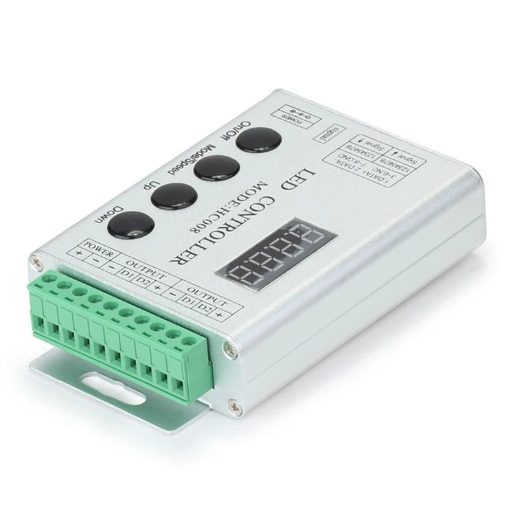
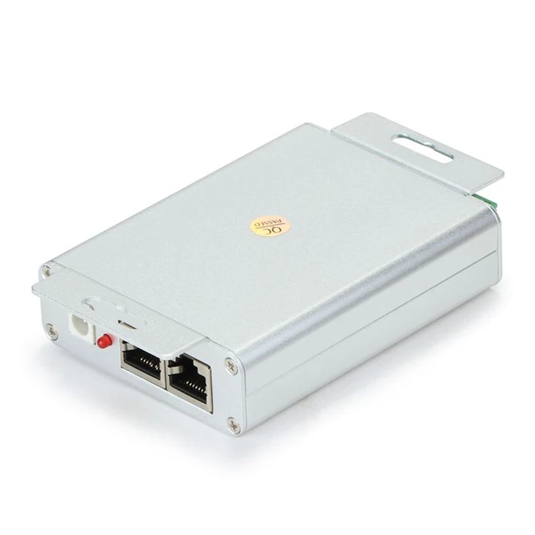
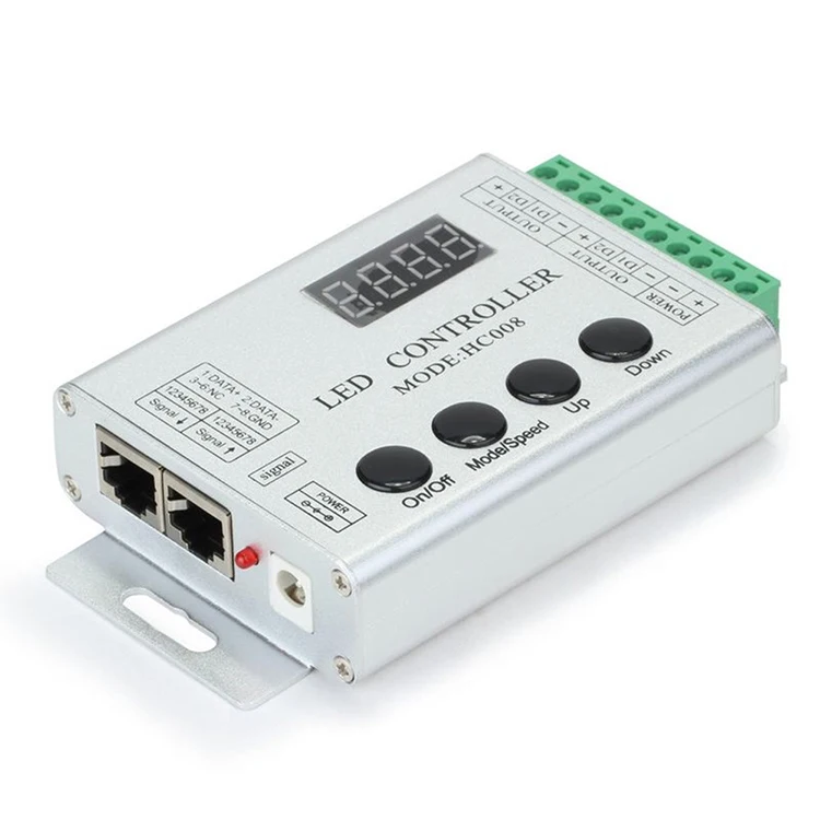
Hot selling DC12V 4Keys RF Remote magic controller HC008 for For 5V 12V WS2811 Pixel Strip Module
Technical Parameters :
| Working temperature | -20-60℃ |
| Supply voltage | DC12~24V |
| Current | <60mA |
| External dimension | L122xW71×H24mm |
| Packing size | L137xW80xH55mm |
| Effects model | 133 |
| Maximum control points | 1024 (Low-speed) points, 2048 (High-speed) points |
| Controlled IC Model | Such as the TM16726,TM2801,TM8806,WS2811, UCS190 |
| Net weight | 180g |
| Gross weight | 270g |

1. Maximum control points:1024(Low-speed) points,2048(High-speed) points.
2. The distance of the first point to controller:Low-speed mode<40m;High-speed mode<20m.(when more than 5 meters,you should use the shielded to connect.)If it is more than the distance,you must add a"TTL level to 485 level" module.
Function of button(controller is in playing state):
(1).ON/OFF:ON/OFF button,it can open or close output.
(2).UP:Mode+/Speed+
(3).DOWN:Mode-1/Speed-
(4).Mode/Speed:Mode adjustable/speed adjustable function switch(The dirst LED displays H for model adjustable,shows S for the speed adjustable.)
Note:After powering,the red light would bright.And each press, the green light flash one time.
the size :

1.Connect the load well wire at first,following by the power wire; Please ensure short circuit can not occurbetween connecting wire before you turn on the power. Then set the steps as follows.
2. Press the "On / off" button to take the controller off before setting the menu.
3. Press the “up”, “down” button one time at the time, and LED would be bright at this moment. Then press the "Mode / Speed" button to get into the menu settings screen.
4.The first setting screen is for “High-speed, low-speed settings”, and the LED would display "S-HI" or "S-LO". Then press the “up” and “down” button to select the mode. (If the IC on the light bar is high-speed mode, you should choose “S-HI”, and choose “S-HI” when low-speed.) The factory default is for the high-speed mode.
5.Continue to press the "Mode / Speed" button to enter the second screen-“Control points setting”. The LED display 4-digit is for the number of control points. To plus or minus the number by pressing the “up” and “down” button (Long pressing can adjust quickly). The factory default is for 50.
6.After setting well, press the "On / off" button to save and exit.
7.There are 4 buttons in total on the control panel, function of each button as below:

1 On/off:It can turn on or turn off the output..
2 Mode/Speed :Mode adjustment / speed adjustment function switch (The first LED displays H for model adjustment, shows S for the speed adjustment.)
3 UP:Mode+/Speed+ button. When in mode regulator function, it is for “Mode+”. When in speed regulator function, it is for “Speed+”.
4 DOWN:Mode-/Speed- button. When in mode regulator function, it is for “Mode”. When in speed regulator function, it is for “Speed-”.
5 Remarks:When power the controller, the red indicator light will be light up, and the green indicator light will be flash when press the button each time.
6 Adopt wireless control method, 4keys in total, function of each key as below:

1 A: Mode adjustment / speed adjustment function switch (The first LED displays H for model adjustment, shows S for the speed adjustment.)
2 B:Mode+/Speed+ button. When in mode regulator function, it is for “Mode+”. When in speed regulator function, it is for “Speed+”.
3 C:Mode-/Speed- button. When in mode regulator function, it is for “Mode-”. When in speed regulator function, it is for “Speed-”.
4 D:On/Off button: It can open or close output.
5 Remarks:When power the controller, the red indicator light will be light up, and the green indicator light will be flash when press the button each time

Application Circuit1:

Application Circuit2: Multi-motor synchronization function application:

( a. Cascade Connection, the master controller just output the signal to the first branch controller, and the next branch controller signal is from the previous branch controller,etc)

( b. Bus connection,all branch controller’s signal output are from the master controller directly.)


Precautions:
To reduce the risk of electric shock, fire or injury to persons, read and follow the warnings and precautions to prevent the occurrence of such events
1 Non-professionals do not open the enclosure.
2 Do not install this controller in a magnetic and high-pressure environments.
3 In order to reduce the component due to a short circuit caused the fire and the risk of damage, make sure the line is connected securely connected.
4 Make sure that the controller altogether good ventilation and proper temperature environment.
5 controller to the room lighting within a distance of 10 meters, the distance between lamps and lighting fixtures, please contact the manufacturer over the pitch range, you can add a signal amplifier.
6 with a controller, make sure to use AC100-230V power supply and ensure that the same transformer and controller connection polarity.
7 Do not plug the power cable in the open, be sure to turn on the power connection is secure and properly before the power
8 When they do not own any unusual repairs, so not warranty.
9 In order to reduce the risk of electric shock, fire or personal injury, read and follow the warnings and precautions to prevent the occurrence of such events



 Share
Share






Customer Reviews total 0 items