Brand: |
none |
Address: |
China |
Min.Order: |
none |
Supply: |
none |
Valid until: |
Long Term |


China
Long Term
2019-10-16 23:46

Scan By Phone


Brand: |
none |
Address: |
China |
Min.Order: |
none |
Supply: |
none |
Valid until: |
Long Term |
| Quantity(Piece) | 1 - 10000 | 10001 - 100000 | 100001 - 300000 | >300000 |
| Est. Time(days) | 2 | 3 | 10 | To be negotiated |
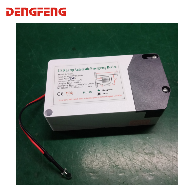
accordance with writing diagram to connect the circuit in strict. The following lines are connected to each po rt:
N—— connect Zero Wire N+ LED external drive zero wire input.
L—— connect the FireWire L+LED external drive fire line input. This line can set a wall switch S. The wall switch only controls the main power, no function on emergency lighting.
(1)——Connect driver output negative terminal
(2)—— Connect driver output positive terminal
(3)——Connect to light source positive terminal
(4)—— Connect to light source negative terminal
1. Diagram wiring, all lines and accessories connected to complete before connecting to the mains test, non-live working.
2: Emergency power supply can not no-load, whether it is testing emergency lighting function or testing the inverter charging function, must be process under load light source
3: Main power line: fire line L and zero line N, connect to main power line directly, these two lines are forbidden to connect the switch
4: Not control by switch S after the light source start emergency lighting
5: Green indicator: main power; Red indicator: charging; yellow: fault.
6: no indicator works in emergency status except emergency lighting


Customer Reviews total 0 items