Brand: |
none |
Address: |
China |
Min.Order: |
none |
Supply: |
none |
Valid until: |
Long Term |


China
Long Term
2019-10-17 02:53

Scan By Phone


Brand: |
none |
Address: |
China |
Min.Order: |
none |
Supply: |
none |
Valid until: |
Long Term |
| Quantity(Sets) | 1 - 30 | 31 - 500 | 501 - 3000 | >3000 |
| Est. Time(days) | 5 | 10 | 15 | To be negotiated |
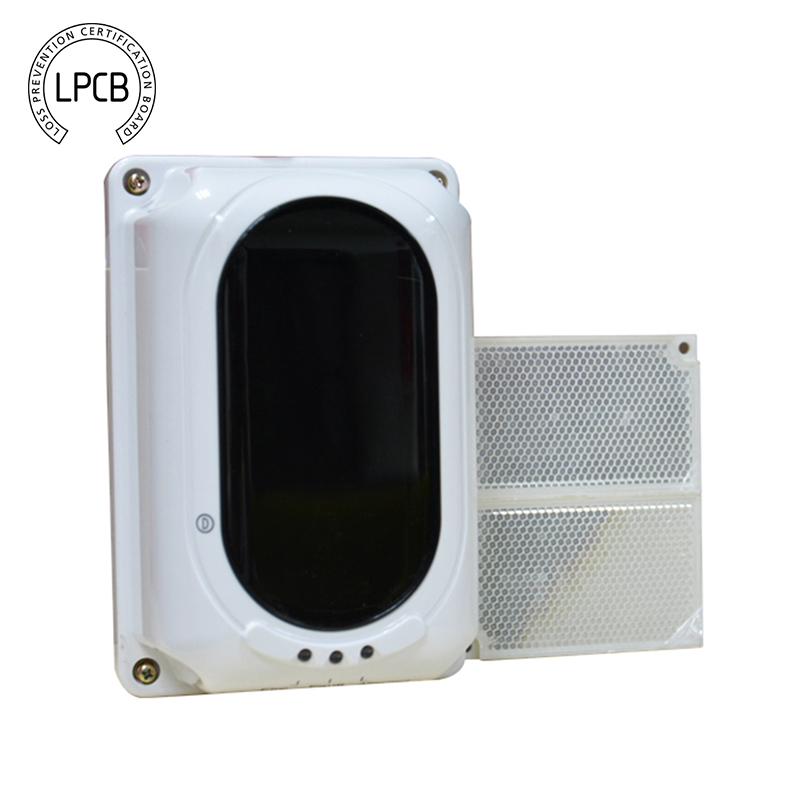
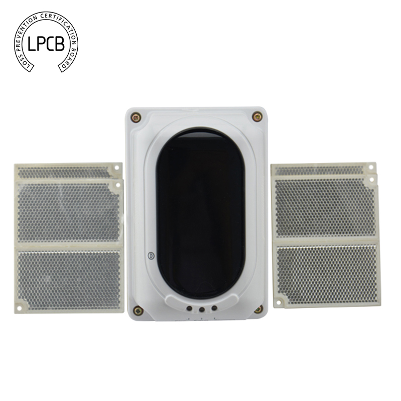
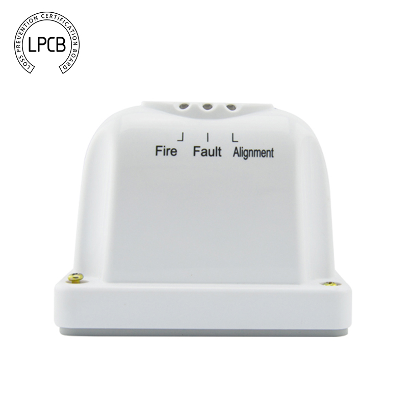
LPCB Approved Conventional Infrared Reflective Beam Smoke Detector


The AW-BK901 reflective optical beam smoke detector incorporates a light transmitter and the detector on the same unit. The light path is created by reflecting light emitted from the transmitter off a retro-reflector, meaning it is reflects light back to its source with a minimum of scattering, which is placed opposite the detector.
In a fire, when smoke falls within the path of the beam detector, some of the light is absorbed or scattered by the smoke particles. This creates a decrease in the received signal, leading to an increase in optical obscuration. This unit decodes or analyzes received signals and compares to the pre-programmed algorithm stored on the processor. Through this algorithm the detector will decide whether fire is defined or not and lead to enablement the corresponding relays and LED indicators. The unit on the operating mode maintaining continually emitting light, care should be taken that the activities in the space do not obstruct the beam or move the device to avoid false operation of the detector.

Mounting of the Beam Detector
1. Using the supplied bracket, mark the position of the fixing holes
2. Drill four holes and insert an 8mm wall plug into each.
3. Fix the mounting bracket to the wall using four ST4x30 screw. Refer to Figure 4
4. Fix the detector base onto the bracket using two M4x12x10 screw. Refer to Figure 5

Mounting of the Reflective Mirror
1. Depending on the project requirement, if the distance between the detector and the reflector mirror is 8m-40m, install one reflector is enough; if the distance is 40m-100m, four reflectors is required. Refer to Figure 6
2. Mark the position of the fixing holes plastic expansion bolts
3. Fix the reflector mirror using two ST4x30 screw, in the case of one unit mirror, do the same step for other mirror if required. Refer to Figure 6.

Cabling Details
Cables should be brought into the detector using the supplied glad cable. The maximum size of the cable which can be terminated is 1.5mm2. Observe the polarity.
1. Terminal D1 (+) and D2 (-) for connecting Power supply [24VDC]
2. Terminal S1 and S2 for connecting handheld programmer
3. Terminal HJ1 and HJ2 for connecting Fire signal relay output [Normally Open]
4. Terminal GZ1 and GZ2 for connecting Fault signal relay output [Normally Open]

To adjust the Span (Distance)
1. Connect the programming cable to S1 and S2 terminal. Polarity is not required and detector must be powered off.
Reference:
Beam Pathway Length Span 1: 8 to 20 meters Short Path
Span 2: 20 to 40 meters Short Path
Span 3: 40 to 70 meters Normal Path
Span 4: 70 to 100 meters Long Path
2. Switch on the programmer, then press button “3” then display “Sensitivity and Distance (m)”.
3. Then enter the desire sensitivity value from 1,2,3 or 4 and then press “Write”. If display “Success”, it means the entered sensitivity is confirmed. If display “Fail”, it means failure to program the sensitivity.

Supplied Accessories
The following accessories are included in the package:
1. Four plastic expansion bolts.
2. Two M4*12*10 three combination cross recessed pan head screws.
3. Four ST4*30 tap cross recessed pan head screws.
4. Mounting Bracket
5. Opaque/Translucent Material
6. Six 4 flat washers.
7. Magnetic Too


1)Sample oder is welcomed to test the quality.
2 ) Flexible technicals adjusting as per customer" s special request.
3) Answer your enquiries, questions and emails in 24 hours
4) Direct control on material, testing, quality, leadtime etc-

Customer Reviews total 0 items