Items | Fabrication Capabilities | Remarks |
Layer Count | 1-10 layers | if your PCB order is over 10 layers, please contact your customer service for quotation. |
Material | FR-4 94V0/ Aluminum | For FPC, HDI, ROGERS, HALOGEN-FREE, HIGH TG ETC., contact your customer service. |
Maximum Size | 500x1100mm | The max. size of PCBGOGO PCB is 50*40cm. and we accept longer PCB board which max. length is 1100MM |
Minimum Size | 3mm*3mm | |
Maximum Panel Size | 50cm*45cm | |
Minimum Panel Size | 7.5*7.5cm | If you need v-cut, this is minimum panel size in PCBGOGO |
Tolerance Size of Board
(Outline) | ±0.2mm | CNC tolerance is ±0.2mm, v-cut tolerance is ±0.5mm |
Board Thickness | 0.4-2.4mm | |
Tolerance Thickness of Board
( t≥1.0mm) | ±10% | Pay attention: as the capability (PTH, solder mask and others) will add the board thickness, we usually use Plus Tolerance. |
Tolerance Thickness of Board
( t≥1.0mm) | ±0.1mm | Pay attention: as the capability (PTH, solder mask and others) will add the board thickness, we usually use Plus Tolerance. |
Min. Line Width | 4mil(0.1mm) | Min. Line Width is 0.1mm;In terms of multi-layer PCBs, Min. Line Width for inner-layer is 0.175mm |
| | 0.1mm/4mil for outer layer. If the minimum line width is less than 6 mil, there will be an extra charge / fee. |
Min. Line Space | 4mil(0.1mm) | Min. Line Spacing is 0.15mm/6mil. If Min. Line Spacing is less than 6mil, it will charge extra fee. |
Outer Layer Copper Thickness | 35um/70um/105um
(1OZ/2OZ/3OZ) | It means the thickness of copper in outer layer. 1 OZ=35um, 2OZ=70um, 3OZ=105um. |
Inner Layer Copper Thickness | 35um/50um
(1OZ/1.5OZ) | Default is 1 OZ, but if you have special requirement, 1.5 OZ is acceptable. |
Drill Diameter Range | 0.2-6.3mm | Min. Size of drill via CNC is 0.2mm. 6.3mm is maximum size. |
Annular Ring | ≥0.1mm(4mil) | If Annular Ring is smaller but there is enough space, there is no limit for the Annular Ring size. But if there is not enough
space coupled with dense lines, the Annular Ring size should be over 0.1mm |
Finished Hole Size | 0.2--6.20mm | Because the copper will cover the surface of hole, the Finished hole size is smaller than it is in Gerber file |
The Size Tolerance of Finished
Hole (CNC | ±0.08mm | Tolerance of Finished Hole Size is ±0.08mm. For example, if the drill in the Gerber file is 0.6mm, the finished drill will be
0.52-0.68mm on standard. |
Solder Mask Type | LPI | LPI is common use in the PCB fabrication. |
Min. Width of Legend | ≥0.15mm | Min. width of legend is 0.15mm, if it is smaller, the legend in the finished board will be not clear. |
Minimum Height of Legend | ≥0.8mm | Min. height of Legend is 0.8mm, if it is smaller, the legend in the finished board will be not clear |
Legend Width/ Height | 1:5 | The suitable proportion of width and height is good for PCB fabrication. |
Space between Trace and
Board Edge | ≥0.3mm(12mil) | Routing: the space between line and frame should be over 0.3mm. V-cut panel: the space between line and v-cut line should be over
0.4mm. |
Panelization | V-scoring, Tab-routing,
Tab-routing with Perforation
(Stamp Holes) | Leave min clearance of 1.6mm between boards for break-routing. For V-score panelization, set the space between boards to be zero. |
Min. aperture in half-hole
technology | 0.6mm | Half-hole is a special technology and the min. aperture must be over 0.6 mm |

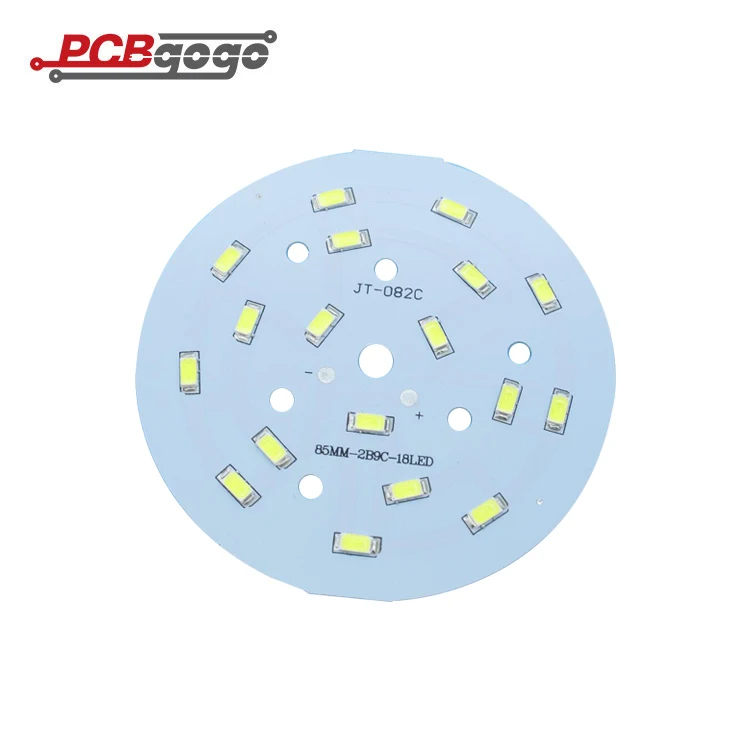
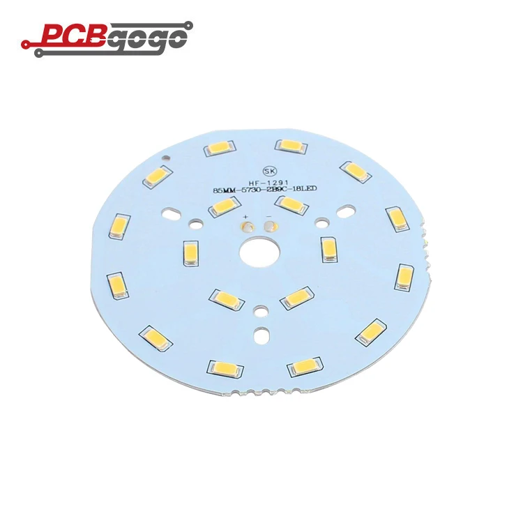
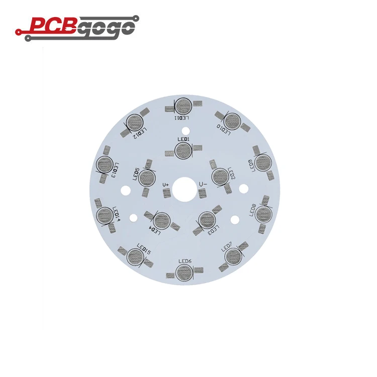

 Share
Share






Customer Reviews total 0 items